The drawing package
The saucer as a set of production drawings: the frame, the electrical system with its strip plan and harness, and the circuit boards. The Engineer's edition tells the story of the build; these sheets are the record you would build it again from. Everything here is as built in October 2026 unless a sheet says otherwise.
| Dwg no. | Title | Sheets | Rev | Status |
|---|---|---|---|---|
| HULL-20-UFO-001 | BUILD RECORD, ENGINEER'S EDITION | 17 | E | RELEASED |
| HULL-20-UFO-010 | FRAME, 2020 EXTRUSION | 4 | A | RELEASED |
| HULL-20-UFO-027 | SKIN, FLOATING PANELS, 2027 | 4 | D | IN WORK |
| HULL-20-UFO-030 | ELECTRICAL, LEDS AND WIRING | 5 | A | RELEASED |
| HULL-20-UFO-040 | CIRCUIT BOARDS: UFO CONTROLLER, BOARDING PASS, SAUCER BADGE | 8 | B | RELEASED |
Drawing HULL-20-UFO-030 sheet 1: one-line power diagram and power budget
| Line | Segment | Px | Per px, full white | Full white | At 42 % cap | Fuse | Feed |
|---|---|---|---|---|---|---|---|
| 1 | RIM | 440 | RGB 60 mA | 26.4 A | 11.1 A | F1 15 A | RING BUS A, TAPS AT FACES 1, 3, 5, 7 |
| 2 | COCKPIT LIP | 115 | RGBW 80 mA | 9.2 A | 3.9 A | F2 10 A | TOP JUNCTION |
| 3 | SPOKES S1 TO S8 | 480 | RGB 60 mA | 28.8 A | 12.1 A | F3 15 A | SPOKE STAR, CENTRE |
| 3 | IRIS | 241 | RGB 60 mA | 14.5 A | 6.1 A | F4 10 A | IRIS PADS, OUTER RING AND CENTRE |
| 4 | PORTHOLES P1 TO P8, EYES | 130 | RGB 60 mA | 7.8 A | 3.3 A | F5 10 A | TOP JUNCTION |
| — | CONTROLLER | — | — | — | — | F6 3 A | BOARD B, USB-C LEAD |
| TOTAL | 1,406 | 86.7 A | 36.4 A | PS1 60 A | FIRMWARE LIMIT 30 A |
| Condition | Cap | Supply current |
|---|---|---|
| UFO-25 SHOW, IDLE, AVERAGE | 42 % | 8.7 A |
| HOLIDAY LIVERY, IDLE, AVERAGE | 42 % | 9.3 A |
| HOLIDAY EVENTS, PEAK: SNOW 10.5, SLEIGH 10.7, GIFT 14.1, GREETING 16.8, MAIL 17.2 | 42 % | 17.2 A MAX |
| ANY EVENT, PEAK | 60 % (NETWORK MAX) | 24.6 A MAX |
| ABDUCTION FLASH FRAME | ANY | 30 A (LIMITER) |
| Revisions | ||||
|---|---|---|---|---|
| Zone | Rev | Description | Date | Approved |
| ALL | A | FIRST ISSUE: AS-BUILT RECORD OF THE 2026 WIRING. 1,406 PX (SPOKES 60 EACH). FOG RELAY AND BEAM POD NOT FITTED | 2026-11-01 | R. DIXON |
Notes
Unless otherwise specified:
- As-built record of the 2026 wiring: the wiring diagram (2026-10-14), the controller stack (2026-10-25) and the firmware's segment table (UfoShow.h, 60 px a spoke).
- All strip power runs from PS1 through F1 to F5. The controller carries data only, and takes its own 5 V through F6.
- 1000 µF across 5 V and 0 V at each strip start (line 1, cockpit, S1, iris, top junction), plus C3 on board B: 6 in all.
- Full white at the 42 % cap keeps every line under its fuse. The firmware scales every frame to keep the supply under 30 A.
- Running currents are the show's frameAmps model (20 mA per channel at 255), not metered. Meter the supply output during an abduction on the ground: 30 A max.
- Last pixel of each line, full white at 42 %: 4.6 V min. Lower, add a tap from ring bus A.
- Mains is the cord and PS1's input only. GFCI outlet. PS1 earth to the cord earth. Glands on the downward face of the box.
- Seal every outdoor joint with adhesive-lined heat shrink.
- Unless otherwise specified
- DC VOLTAGES TO 0 V BUS
WIRE: STRANDED COPPER, AWG
FUSES: ATC BLADE, INLINE
DO NOT SCALE DRAWING - Drawn
- R. DIXON
- 2026-11-01
- Checked
- R. DIXON
- 2026-11-01
- Approved
- R. DIXON
- 2026-11-01
- Owner
- HULL/20
SPACEWAYS - Document type
- ELECTRICAL DIAGRAM
- Status
- RELEASED
- Units
- AS NOTED
- Projection
- THIRD ANGLE
PROJECTION - Title
- ELECTRICAL, ONE-LINE AND POWER
- Size
- B
- Scale
- NONE
- Sheet
- 1 OF 5
- Dwg no.
- HULL-20-UFO-030
- Rev
- A
Drawing HULL-20-UFO-030 sheet 2: controller stack, assembly
| Find no. | Qty | Part | Notes |
|---|---|---|---|
| 1 | 1 | BOX PLATE | SIZE TBD (MEASURE); DRAWN AS A PHANTOM SIZE ONLY |
| 2 | 8 | M3 NYLON SCREW | PAN HEAD, FROM UNDER THE PLATE |
| 3 | 4 | M3 NYLON STANDOFF 10 | BOARD B (STACK PAGE) |
| 4 | 4 | M3 NYLON STANDOFF 35 | BOARD A, CORNERS OUTSIDE B (STACK PAGE) |
| 5 | 1 | BOARD B, PROTOTYPE BOARD | R1-R4 330 STANDING, C3; STRIP + POWER WIRES SOLDERED IN |
| 6 | 4 | R1-R4 330 Ω | DIN0207 STANDING |
| 7 | 1 | C3 ELECTROLYTIC | 100 µF OR BIGGER |
| 8 | 1 | BOARD A, PROTOTYPE BOARD, 30 ROWS | BREADBOARD LAYOUT, RAILS BOTH SIDES |
| 9 | 2 | 15-PIN FEMALE HEADER | COLUMNS D AND H, ROWS 1-15 |
| 10 | 1 | DIP-14 SOCKET | U1, ROWS 17-23 |
| 11 | 1 | U1 74AHCT125 | DIP-14 |
| 12 | 1 | C1 0.1 µF | CERAMIC DISC |
| 13 | 1 | ESP32-S3 MODULE BOARD, NANO FORM FACTOR | ON THE HEADERS, POWERED BY ITS OWN USB-C (LEAD FROM B ROWS 1/3) |
| 14 | 4 | M3 NYLON SCREW | PAN HEAD, THROUGH A INTO ITS STANDOFFS |
| - | 4 | M3 NYLON SCREW | PAN HEAD, THROUGH B INTO ITS STANDOFFS |
Notes
Unless otherwise specified:
- Two stacked prototype boards. Every wire is soldered straight into its hole: no screw terminals. Hole-by-hole build in the controller stack guide.
- U1 stays out of its socket and A1 off its headers until the bench test: no continuity between +5 V and 0 V on either board.
- The stack sits in the IP67 box on the two box rails over the core ring, under the deck (drawing 010). Box plate size to be measured: drawn in phantom, SIZE TBD.
- Unless otherwise specified
- DC VOLTAGES TO 0 V BUS
WIRE: STRANDED COPPER, AWG
FUSES: ATC BLADE, INLINE
DO NOT SCALE DRAWING - Drawn
- R. DIXON
- 2026-11-01
- Checked
- R. DIXON
- 2026-11-01
- Approved
- R. DIXON
- 2026-11-01
- Owner
- HULL/20
SPACEWAYS - Document type
- ASSEMBLY DRAWING
- Status
- RELEASED
- Units
- AS NOTED
- Projection
- THIRD ANGLE
PROJECTION - Title
- CONTROLLER STACK, ASSEMBLY
- Size
- B
- Scale
- NONE
- Sheet
- 2 OF 5
- Dwg no.
- HULL-20-UFO-030
- Rev
- A
Drawing HULL-20-UFO-030 sheet 3: controller schematic
| Pin | Name | Net |
|---|---|---|
| 1 | 1OE | 0 V |
| 2 | 1A | A1 D2, GPIO5 |
| 3 | 1Y | R1, LINE 1 |
| 4 | 2OE | 0 V |
| 5 | 2A | A1 D3, GPIO6 |
| 6 | 2Y | R2, LINE 2 |
| 7 | GND | 0 V |
| 8 | 3Y | R3, LINE 3 |
| 9 | 3A | A1 D4, GPIO7 |
| 10 | 3OE | 0 V |
| 11 | 4Y | R4, LINE 4 |
| 12 | 4A | A1 D5, GPIO8 |
| 13 | 4OE | 0 V |
| 14 | VCC | +5 V |
Notes
- Level shift: the ESP32 drives 3.3 V logic; a WS2812B at 5 V wants 0.7 × VDD = 3.5 V for a high. The 74AHCT125 has TTL input thresholds and a full 5 V output swing.
- The 330 Ω series resistors take the ringing off the edges on the way down the cables.
- Four RMT channels send all four lines at once. Line 3 (721 px, 21.6 ms) sets the frame time.
- Bench test passed 2026-10-25: test firmware lights each line in its own colour (rim green, cockpit blue, spokes purple, portholes cyan).
- Unless otherwise specified
- DC VOLTAGES TO 0 V BUS
WIRE: STRANDED COPPER, AWG
FUSES: ATC BLADE, INLINE
DO NOT SCALE DRAWING - Drawn
- R. DIXON
- 2026-11-01
- Checked
- R. DIXON
- 2026-11-01
- Approved
- R. DIXON
- 2026-11-01
- Owner
- HULL/20
SPACEWAYS - Document type
- SCHEMATIC
- Status
- RELEASED
- Units
- AS NOTED
- Projection
- THIRD ANGLE
PROJECTION - Title
- CONTROLLER, SCHEMATIC
- Size
- B
- Scale
- NONE
- Sheet
- 3 OF 5
- Dwg no.
- HULL-20-UFO-030
- Rev
- A
Drawing HULL-20-UFO-030 sheet 4: LED strip plan and index map
| Line | Pin | Index | Segment | Physical order | Strip |
|---|---|---|---|---|---|
| 1 | D2, GPIO5 | 0 TO 439 | RIM | CLOCKWISE FROM THE AFT FLAT'S LEFT CORNER, 55 PER FACE. FIRMWARE SHIFTS IT 1/16 TURN (RIM_A0) SO 0 IS MID-AFT | RGB REEL 1 (300) THEN REEL 2 (140) |
| 2 | D3, GPIO6 | 0 TO 114 | COCKPIT LIP | ONCE ROUND THE 24 IN DOME LIP FROM THE TOP JUNCTION | RGBW, 4 BYTES A PIXEL |
| 3 | D4, GPIO7 | 0 TO 479 | SPOKES | S1 0 TO 59 CENTRE TO RIM, S2 60 TO 119 RIM TO CENTRE, AND SO ON: S1, S3, S5, S7 OUTWARD, S2, S4, S6, S8 INWARD | RGB REEL 3 (S1 TO S5), REEL 4 (S6 TO S8) |
| 3 | 480 TO 720 | IRIS | OUTER RING FIRST: RINGS OF 60, 48, 40, 32, 24, 16, 12, 8, 1 (FIRMWARE REMAPS TO CENTRE FIRST) | 241-PX DISC | |
| 4 | D5, GPIO8 | 0 TO 127 | PORTHOLES | P1 TO P8, 16 EACH, CHAINED FROM THE TOP JUNCTION | 16-PX RINGS, 8 OF 10 |
| 4 | 128 TO 129 | EYES | THE PILOT'S TWO EYE PIXELS, END OF THE CHAIN | — |
Notes
- Line 1 runs uncut through each corner gap between the rim channels. Reel 1 joins reel 2 at their factory connectors on face 6.
- Spokes are 60 px each as built (one metre of 60/m strip), not the 56 of the first plan.
- Belly jumpers, 22 AWG 3-core (5 V, 0 V, data): at the rim S1 to S2, S3 to S4, S5 to S6, S7 to S8, about 33 in; at the hub S2 to S3, S4 to S5, S6 to S7, about 5 in; S8 to the iris, about 7 in.
- Porthole P1's place on the ring is as wired; the firmware's PORT_A0 sets where the show starts.
- Count from the input end, the end the strip's arrows point away from. Cut through the middle of the copper pads. Seal every cut end.
- Unless otherwise specified
- DC VOLTAGES TO 0 V BUS
WIRE: STRANDED COPPER, AWG
FUSES: ATC BLADE, INLINE
DO NOT SCALE DRAWING - Drawn
- R. DIXON
- 2026-11-01
- Checked
- R. DIXON
- 2026-11-01
- Approved
- R. DIXON
- 2026-11-01
- Owner
- HULL/20
SPACEWAYS - Document type
- WIRING DIAGRAM
- Status
- RELEASED
- Units
- AS NOTED
- Projection
- THIRD ANGLE
PROJECTION - Title
- LED STRIP PLAN
- Size
- B
- Scale
- NONE
- Sheet
- 4 OF 5
- Dwg no.
- HULL-20-UFO-030
- Rev
- A
Drawing HULL-20-UFO-030 sheet 5: cable schedule and solder points
| Wire | From | To | Cond. | Gauge | Colour | Length | Notes |
|---|---|---|---|---|---|---|---|
| W1 | F1 | RING BUS A START, AFT-LEFT CORNER | 2 | 14 AWG | RED / BLACK | 1.5 M | |
| W2 | RING BUS A | ROUND THE INSIDE OF THE RIM | 2 | 14 AWG | RED / BLACK | 7.5 M | |
| W3 TO W6 | RING BUS A | LINE 1 TAPS, FACES 1, 3, 5, 7 | 2 EACH | 18 AWG | RED / BLACK | SHORT | PART OF THE 8 M OF 18 AWG |
| W7 | F2 | TOP JUNCTION (COCKPIT) | 2 | 14 AWG | RED / BLACK | 1.5 M | UP THROUGH A DECK GLAND |
| W8 | F3 | SPOKE STAR, CENTRE | 2 | 14 AWG | RED / BLACK | SHORT | STAR IS OVER THE BEAM PORT |
| W9 | F4 | IRIS 5 V / 0 V PADS | 2 | 14 AWG | RED / BLACK | 1.5 M | OUTER RING AND CENTRE |
| W10 | F5 | TOP JUNCTION | 2 | 14 AWG | RED / BLACK | 1.5 M | UP THROUGH A DECK GLAND |
| W11, W12 | TOP JUNCTION | P1 AND P5 POWER | 2 EACH | 18 AWG | RED / BLACK | SHORT | |
| W13 | F6 | BOARD B, ROW 1 a (+5 V), ROW 3 a (0 V) | 2 | 20 AWG | RED / BLACK | IN BOX | THEN THE USB-C LEAD TO A1 |
| W14 | J1 | LINE 1 IN, AFT-LEFT CORNER | 3 | 22 AWG | 3-CORE | PART OF 6 M | DATA, 0 V, SPARE |
| W15 | J2 | LINE 2 IN, TOP JUNCTION | 3 | 22 AWG | 3-CORE | PART OF 6 M | DATA, 0 V, SPARE |
| W16 | J3 | LINE 3 IN, S1 AT THE CENTRE | 3 | 22 AWG | 3-CORE | PART OF 6 M | DATA, 0 V, SPARE |
| W17 | J4 | LINE 4 IN, TOP JUNCTION TO P1 | 3 | 22 AWG | 3-CORE | PART OF 6 M | DATA, 0 V, SPARE |
| W18 TO W21 | S1, S3, S5, S7 RIM END | S2, S4, S6, S8 RIM END | 3 | 22 AWG | 3-CORE | ≈ 33 IN EACH | 5 V, 0 V, DATA |
| W22 TO W24 | S2, S4, S6 CENTRE END | S3, S5, S7 CENTRE END | 3 | 22 AWG | 3-CORE | ≈ 5 IN EACH | 5 V, 0 V, DATA |
| W25 | S8 CENTRE END | IRIS DATA IN | 3 | 22 AWG | 3-CORE | ≈ 7 IN | |
| W26 | P1 | P2 … P8, THEN THE EYES | 3 | 22 AWG | 3-CORE | ≈ 6 M | CHAIN |
| W27 | MAINS CORD | PS1 L, N, PE | 3 | CORD | — | TO OUTLET | GFCI, DRIP LOOP |
| Point | Signal | Board B hole | Other end |
|---|---|---|---|
| J5 | +5 V IN | ROW 1, HOLE a | F6 (W13) |
| J5 | 0 V IN | ROW 3, HOLE a | 0 V BUS (W13) |
| J1 | DATA | ROW 1, HOLE j | LINE 1 DATA IN |
| J1 | 0 V | ROW 3, HOLE j | LINE 1 0 V |
| J2 | DATA | ROW 5, HOLE j | LINE 2 DATA IN |
| J2 | 0 V | ROW 7, HOLE j | LINE 2 0 V |
| J3 | DATA | ROW 9, HOLE j | LINE 3 DATA IN |
| J3 | 0 V | ROW 11, HOLE j | LINE 3 0 V |
| J4 | DATA | ROW 13, HOLE j | LINE 4 DATA IN |
| J4 | 0 V | ROW 15, HOLE j | LINE 4 0 V |
| Wire | Signal |
|---|---|
| 1 | +5 V, FROM ITS FUSED FEED |
| 2 | 0 V |
| 3 | DATA, FROM J1 TO J4 OR THE JUMPER BEFORE IT |
Notes
- Wire totals with slack: about 20 m of 14 AWG pair, 8 m of 18 AWG pair, 20 m of 22 AWG 3-core (buy 100 ft).
- Every data run leaves board B with its own 0 V wire beside it; that 0 V is a reference, not the strip's power.
- Leave 2 in of slack at each jumper end. Solder, then seal.
- Unless otherwise specified
- DC VOLTAGES TO 0 V BUS
WIRE: STRANDED COPPER, AWG
FUSES: ATC BLADE, INLINE
DO NOT SCALE DRAWING - Drawn
- R. DIXON
- 2026-11-01
- Checked
- R. DIXON
- 2026-11-01
- Approved
- R. DIXON
- 2026-11-01
- Owner
- HULL/20
SPACEWAYS - Document type
- WIRING LIST
- Status
- RELEASED
- Units
- AS NOTED
- Projection
- THIRD ANGLE
PROJECTION - Title
- CABLE SCHEDULE AND SOLDER POINTS
- Size
- B
- Scale
- NONE
- Sheet
- 5 OF 5
- Dwg no.
- HULL-20-UFO-030
- Rev
- A
Drawing HULL-20-UFO-010 sheet 1: frame assembly and parts list
| Revisions | ||||
|---|---|---|---|---|
| Zone | Rev | Description | Date | Approved |
| ALL | A | FIRST ISSUE: AS-BUILT RECORD OF THE 2020 FRAME, CUT 2026-10-17, DRILLED 2026-10-18. G RISER POSTS CUT, NOT FITTED: THE DOME BOLTS TO THE DECK | 2026-11-01 | R. DIXON |
| Find | Qty | Description | Length | From | Where |
|---|---|---|---|---|---|
| A | 8 | RIM, 2020 | 900 [35⅜] | BARS 1 TO 8 | OCTAGON; OUTER SIDE 916.6 [36.1] |
| B | 8 | SPOKE, 2020 | 900 [35⅜] | BARS 9 TO 16 | RIM MID-SIDE TO CORE RING, FLUSH WITH THE RIM TOP |
| C | 8 | HUB RING, 2020 | 300 [11¾] | OFFCUTS 1 TO 8 | OCTAGON ON THE POSTS, 162 [6⅜] UP |
| D | 8 | CORE RING, 2020 | 137.8 [5⅜] | OFFCUTS 9 TO 16 | OCTAGON AT THE CENTRE, RIM LEVEL |
| E | 8 | HUB POST, 2020 | 142 [5⅝] | OFFCUTS 9 TO 16 | ON EACH SPOKE, UNDER THE HUB RING |
| F | 4 | PLATE LEG, 2020 | 90 [3½] | BAR 18 | CORE RING D2, D4, D6, D8 DOWN TO THE CENTRE PLATE |
| G | 8 | RISER POST, 2020 | 95 [3¾] | BARS 17, 18 | CUT, NOT FITTED, NOT SHOWN |
| H | 2 | BOX RAIL, 2020 | 373 [14⅝] | BAR 19 | ACROSS THE CORE RING TOP, 39.9 OFF CENTRE |
| K | 8 | PORTHOLE POST, 2020 | 60 [2⅜] | BAR 18 | ON EACH SPOKE, 744 FROM CENTRE |
| L | 4 | LEG POST, 2020 | 150 [5⅞] | BARS 17, 20 | UNDER THE 4 LIFT SPOKES, 940 FROM CENTRE |
| X | 4 | LEG EXTENSION, 2020 | 400 [15¾] | BARS 17, 19, 20 | ON L, LANDED MODE |
| BR | 24 | BRACKET, 135°, FOR 2020, 60 × 16 × 6 | — | — | J1, J6, J7 |
| PE | 8 | PAD EYE, 316, M6 | — | — | J12, TOP AND UNDER, B1, B3, B5, B7 AT 814 |
| FT | 4 | FOOT, LEVELLING, M6, Ø50 SWIVEL PAD | — | — | INTO X (LANDED) OR L (ROOF) |
| 1 | 48 | SCREW, FLAT HEAD, M5 × 35, 304, WITH NUT, NYLOCK, M5 | — | — | 2 PER BRACKET |
| 2 | 36 | SCREW, SOCKET HEAD, M6 × 40, 304 | — | — | J3, J4, J8, J10, J12 |
| 3 | 8 | SCREW, FLAT HEAD, M6 × 40, 304 | — | — | J2, FLUSH UNDER THE RIM LEDS |
| 4 | 12 | SCREW, BUTTON HEAD, M6 × 50, 304 | — | — | J5 (8); J11 WITH NYLOCK (4) |
| 5 | 12 | SCREW, BUTTON HEAD, M6 × 25, STAINLESS | — | — | J8 (4), J10 (8). J9 NOT BUILT |
| 6 | 4 | STUD, GRUB, M6 × 30 | — | — | L TO X, LANDED MODE |
Notes
Unless otherwise specified:
- As built: every piece cut to this list, 20 bars of 1220 mm 2020 T-slot (slot 6), square cuts, 3 mm kerf.
- Rim octagon 2213 [87⅛] across flats, equal three ways; 2397 [94⅜] across points. Core ring about 373 across flats. H box rails 39.9 either side of centre, 373 long (supersedes the 50 / 333 of the first frame drawing).
- No sloped joints: flat rings, radial spokes and vertical posts, all at 90° or 135°. Legs drawn in landed mode: L, M6 × 30 grub stud, X and foot; roof mode is L and foot.
- G riser posts cut but not fitted: the dome lip bolts to the deck. Deck and centre plate as built in ¾ in plywood.
- Every M6: medium-strength threadlocker. Snug every joint in a step, check it, then tighten.
- Snag-proofing: deburr every cut end; round and tape the 16 outside corners of the rim and hub ring; cap the 48 M5 tails.
- Bare frame, extrusion and hardware, 26 to 29 lb.
- Unless otherwise specified
- DIMENSIONS IN MM [IN]
TOLERANCES: X ±1 X.X ±0.5
ANGLES ±0.5° AS BUILT
DO NOT SCALE DRAWING - Drawn
- R. DIXON
- 2026-11-01
- Checked
- R. DIXON
- 2026-11-01
- Approved
- R. DIXON
- 2026-11-01
- Owner
- HULL/20
SPACEWAYS - Document type
- ASSEMBLY DRAWING
- Status
- RELEASED
- Units
- MM [IN]
- Projection
- THIRD ANGLE
PROJECTION - Title
- FRAME, 2020 EXTRUSION, ASSEMBLY
- Size
- B
- Scale
- AS SHOWN
- Sheet
- 1 OF 4
- Dwg no.
- HULL-20-UFO-010
- Rev
- A
Drawing HULL-20-UFO-010 sheet 2: plan, elevation and joint schedule
| Joint | Qty | Where | How | Fasteners each |
|---|---|---|---|---|
| J1 | 8 | RIM CORNER | 135° BRACKET ON THE INNER FACES, BOLTED FROM OUTSIDE | 1 × BR, 2 × FIND 1 |
| J2 | 8 | SPOKE TO RIM | FROM OUTSIDE THE RIM INTO THE SPOKE'S TAPPED END, COUNTERSUNK FLUSH | 1 × FIND 3 |
| J3 | 8 | SPOKE TO CORE RING | FROM INSIDE THE CORE RING INTO THE SPOKE'S IN END | 1 × FIND 2 |
| J4 | 8 | HUB POST TO SPOKE | UP THROUGH THE SPOKE INTO THE POST | 1 × FIND 2 |
| J5 | 8 | DECK AND HUB RING TO POST | DOWN THROUGH THE DECK AND THE RING INTO THE POST | 1 × FIND 4 |
| J6 | 8 | HUB RING CORNER | AS J1 | 1 × BR, 2 × FIND 1 |
| J7 | 8 | CORE RING CORNER | AS J1 | 1 × BR, 2 × FIND 1 |
| J8 | 4 | PLATE LEG | DOWN THROUGH THE CORE RING, 29 FROM ONE END, INTO THE LEG; UP THROUGH THE PLATE | 1 × FIND 2, 1 × FIND 5 |
| J9 | 8 | RISER POST | NOT BUILT: THE DOME LIP BOLTS TO THE DECK | — |
| J10 | 8 | PORTHOLE POST | UP THROUGH THE SPOKE; DOWN THROUGH THE PORTHOLE PLATE | 1 × FIND 2, 1 × FIND 5 |
| J11 | 2 | BOX RAIL ON CORE RING | THROUGH RAIL AND RING AT EACH END, NYLOCK | 2 × FIND 4 |
| J12 | 4 | LIFT POINT | EVERY OTHER SPOKE, 1000 FROM CENTRE: PAD EYE ON TOP, ONE UNDER, THROUGH BOLTS | 2 × FIND 2, 2 × PE |
- Unless otherwise specified
- DIMENSIONS IN MM [IN]
TOLERANCES: X ±1 X.X ±0.5
ANGLES ±0.5° AS BUILT
DO NOT SCALE DRAWING - Drawn
- R. DIXON
- 2026-11-01
- Checked
- R. DIXON
- 2026-11-01
- Approved
- R. DIXON
- 2026-11-01
- Owner
- HULL/20
SPACEWAYS - Document type
- ASSEMBLY DRAWING
- Status
- RELEASED
- Units
- MM [IN]
- Projection
- THIRD ANGLE
PROJECTION - Title
- FRAME, PLAN, ELEVATION, JOINTS
- Size
- B
- Scale
- AS SHOWN
- Sheet
- 2 OF 4
- Dwg no.
- HULL-20-UFO-010
- Rev
- A
Drawing HULL-20-UFO-010 sheet 3: section S-S, detail U, drill table
| Piece | Which | From ref | Through | Ø | For | Holes |
|---|---|---|---|---|---|---|
| A | ALL 8 | 450, CENTRE | SIDE TO SIDE | 6.5 | J2; COUNTERSINK THE OUTSIDE FACE | 8 |
| B | ALL 8 | 186 FROM IN | TOP TO BOTTOM | 6.5 | J4 HUB POST (372 FROM CENTRE) | 8 |
| B | ALL 8 | 558 FROM IN | TOP TO BOTTOM | 6.5 | J10 PORTHOLE POST (744 FROM CENTRE) | 8 |
| B | B1, B3, B5, B7 | 754 FROM IN | TOP TO BOTTOM | 6.5 | LEG POST L (940 FROM CENTRE) | 4 |
| B | B1, B3, B5, B7 | 814 FROM IN, FROM THE PAD EYE | TOP TO BOTTOM | 6.5 | J12 PAD EYES (1000 FROM CENTRE) | 8 |
| C | ALL 8 | 150, CENTRE | TOP TO BOTTOM | 6.5 | J5 | 8 |
| D | ALL 8 | 68.9, CENTRE | SIDE TO SIDE | 6.5 | J3 | 8 |
| D | ALL 8 | 29 FROM THE DOT END | TOP TO BOTTOM | 6.5 | J8 (D2, D4, D6, D8); J11 (D1, D5) | 8 |
| D | D1, D5 | 29 FROM THE OTHER END | TOP TO BOTTOM | 6.5 | J11, DRILLED WITH THE RAIL | 2 |
| H | BOTH | 10 FROM EACH END | TOP TO BOTTOM | 6.5 | J11, DRILLED WITH THE RING | 4 |
| A, C, D | ALL | ≈ 45 FROM EACH END, THROUGH THE BRACKET | SIDE TO SIDE | 5.5 | J1, J6, J7; COUNTERSINK OUTSIDE | 48 |
- Unless otherwise specified
- DIMENSIONS IN MM [IN]
TOLERANCES: X ±1 X.X ±0.5
ANGLES ±0.5° AS BUILT
DO NOT SCALE DRAWING - Drawn
- R. DIXON
- 2026-11-01
- Checked
- R. DIXON
- 2026-11-01
- Approved
- R. DIXON
- 2026-11-01
- Owner
- HULL/20
SPACEWAYS - Document type
- DETAIL DRAWING
- Status
- RELEASED
- Units
- MM [IN]
- Projection
- THIRD ANGLE
PROJECTION - Title
- FRAME, SECTION S-S, DRILL TABLE
- Size
- B
- Scale
- AS SHOWN
- Sheet
- 3 OF 4
- Dwg no.
- HULL-20-UFO-010
- Rev
- A
Drawing HULL-20-UFO-010 sheet 4: detail T, tap table, cut plan
| Pieces | Ends | Thread | Depth |
|---|---|---|---|
| B, E, F, G, K, L, X: BOTH ENDS | 88 | M6 × 1.0, DRILL-AND-TAP BIT | 25 |
| A, C, D, H | 0 | NEVER TAPPED: SCREWS GO THROUGH THEM | — |
| Bars | Pieces | Left |
|---|---|---|
| 1 TO 8 | A 900, C 300 | 14 |
| 9 TO 16 | B 900, D 137.8, E 142 | ≈ 31 |
| 17 | 5 × G 95, X 400, 2 × L 150 | ≈ 20 |
| 18 | 3 × G 95, 4 × F 90, 8 × K 60 | ≈ 50 |
| 19 | 2 × H 373, X 400 | ≈ 68 |
| 20 | 2 × X 400, 2 × L 150 | ≈ 110 |
- Unless otherwise specified
- DIMENSIONS IN MM [IN]
TOLERANCES: X ±1 X.X ±0.5
ANGLES ±0.5° AS BUILT
DO NOT SCALE DRAWING - Drawn
- R. DIXON
- 2026-11-01
- Checked
- R. DIXON
- 2026-11-01
- Approved
- R. DIXON
- 2026-11-01
- Owner
- HULL/20
SPACEWAYS - Document type
- DETAIL DRAWING
- Status
- RELEASED
- Units
- MM [IN]
- Projection
- THIRD ANGLE
PROJECTION - Title
- FRAME, DETAIL T, TAP AND CUT
- Size
- B
- Scale
- AS SHOWN
- Sheet
- 4 OF 4
- Dwg no.
- HULL-20-UFO-010
- Rev
- A
Drawing HULL-20-UFO-040 sheet 1: UFO controller rev A, fabrication
| Tool | Finished Ø | Holes | Plating |
|---|---|---|---|
| T1 | 0.30 | 1 | PTH |
| T2 | 0.80 | 44 | PTH |
| T3 | 1.00 | 32 | PTH |
| T4 | 1.15 | 2 | PTH |
| T5 | 1.30 | 15 | PTH |
| T6 | 3.20 | 3 | PTH |
| TOTAL | 97 |
| Revisions | ||||
|---|---|---|---|---|
| Zone | Rev | Description | Date | Approved |
| ALL | A | FIRST ISSUE: UFO CONTROLLER REV A (DESIGN, NOT BUILT) AND BOARDING PASS REV B (100 ASSEMBLED, ORDERED 2026-10-19), FROM THEIR FABRICATION DATA | 2026-11-01 | R. DIXON |
| 6-8 | B | SHEETS 6 TO 8 ADDED: SAUCER BADGE REV A (DESIGN). PART NAMES GENERIC ON ALL SHEETS | 2026-11-01 | R. DIXON |
| Layer | Type | Thickness | Colour / material |
|---|---|---|---|
| F.SILKS | LEGEND | — | WHITE |
| F.MASK | SOLDER MASK | 0.01 | BLACK |
| F.CU | COPPER, 1 OZ | 0.035 | — |
| CORE | DIELECTRIC | TO SUIT | FR-4 |
| B.CU | COPPER, 1 OZ | 0.035 | — |
| B.MASK | SOLDER MASK | 0.01 | BLACK |
| B.SILKS | LEGEND | — | WHITE |
| FINISHED BOARD | 1.6 | HASL LEAD-FREE |
Fabrication notes
Unless otherwise specified:
- Fabricate per IPC-6012 class 2; accept per IPC-A-600 class 2.
- FR-4, 2 layers, 1.6 finished thickness. Copper 1 oz (35 µm) outer, finished.
- Surface finish HASL lead-free. Solder mask black both sides; legend white both sides. Vias tented.
- Hole sizes are finished sizes. Board outline per the Edge_Cuts layer; the outline governs.
- 100 % electrical test against the netlist. No fabricator marking on the board.
- Design only: the controller flying in the saucer is the hand-wired stack, drawing 030 sheet 2. This board drawing is from 2026-10-17, before the screw terminals came off.
- Unless otherwise specified
- DIMENSIONS IN MM
TOLERANCES: X.X ±0.2 X.XX ±0.1
PER IPC-6012 CLASS 2
DO NOT SCALE DRAWING - Drawn
- R. DIXON
- 2026-11-01
- Checked
- R. DIXON
- 2026-11-01
- Approved
- R. DIXON
- 2026-11-01
- Owner
- HULL/20
SPACEWAYS - Document type
- FABRICATION DRAWING
- Status
- DESIGN
- Units
- MM
- Projection
- THIRD ANGLE
PROJECTION - Title
- UFO CONTROLLER REV A, FABRICATION
- Size
- B
- Scale
- 1:1
- Sheet
- 1 OF 8
- Dwg no.
- HULL-20-UFO-040
- Rev
- B
Drawing HULL-20-UFO-040 sheet 2: UFO controller rev A, assembly
| Find no. | Qty | Part | Notes |
|---|---|---|---|
| 1 | 1 | BOX PLATE | SIZE TBD (MEASURE); PHANTOM SIZE ONLY |
| 2 | 3 | M3 NYLON SCREW | FROM UNDER THE PLATE |
| 3 | 3 | M3 NYLON STANDOFF 10 | AT H1-H3 |
| 4 | 1 | UFO-CONTROLLER REVA BOARD | 130.3 X 83.0, 2 LAYERS, 1.6 |
| 5 | 2 | DIP-14 SOCKET, U1/U2 | 74AHCT125N IN DIP SOCKETS (SOCKET MODEL) [U1, U2] |
| 6 | 2 | 15-PIN FEMALE HEADER | JN1/JN2, THE ESP32-S3 BOARD'S SOCKETS [JN1, JN2] |
| 7 | 6 | SCREW TERMINAL 2-POS 5.08 | J0 5V IN, J1-J4 STRIPS, J5 BEAM (UNUSED AS BUILT) [J0, J1, J2, J3, J4, J5] |
| 8 | 1 | SCREW TERMINAL 3-POS 5.08 | J6 FOG RELAY (UNUSED AS BUILT) [J6] |
| 9 | 6 | RESISTOR DIN0207 | R1-R4 330, R5/R6 10K, HORIZONTAL [R1, R2, R3, R4, R5, R6] |
| 10 | 2 | C1/C2 0.1 µF | CERAMIC DISC [C1, C2] |
| 11 | 1 | C3 1000 µF 16 V | RADIAL D10 [C3] |
| 12 | 1 | ESP32-S3 MODULE BOARD, NANO FORM FACTOR | ON JN1/JN2; USB-C POWER LEAD FROM J7 |
| 13 | 3 | M3 NYLON SCREW | INTO THE STANDOFFS |
Notes
- Every component model placed by KiCad from the board file.
- Box plate size to be measured: drawn in phantom, SIZE TBD.
- Circuit as drawing 030 sheet 3, with screw terminals J0 to J6 and the fog and beam parts fitted (U2, R5, R6, J5, J6). J5 and J6 are unused as built.
- U1 and U2 in DIP-14 sockets, notch as the silk. C3 stripe to 0 V.
- Unless otherwise specified
- DIMENSIONS IN MM
TOLERANCES: X.X ±0.2 X.XX ±0.1
PER IPC-6012 CLASS 2
DO NOT SCALE DRAWING - Drawn
- R. DIXON
- 2026-11-01
- Checked
- R. DIXON
- 2026-11-01
- Approved
- R. DIXON
- 2026-11-01
- Owner
- HULL/20
SPACEWAYS - Document type
- ASSEMBLY DRAWING
- Status
- DESIGN
- Units
- MM
- Projection
- THIRD ANGLE
PROJECTION - Title
- UFO CONTROLLER REV A, ASSEMBLY
- Size
- B
- Scale
- 1:1
- Sheet
- 2 OF 8
- Dwg no.
- HULL-20-UFO-040
- Rev
- B
Drawing HULL-20-UFO-040 sheet 3: boarding pass rev B, fabrication
| Finished Ø | Holes | Plating |
|---|---|---|
| 0.30 | 2 | PTH |
| 0.65 | 2 | NPTH |
| Layer | Type | Thickness | Colour / material |
|---|---|---|---|
| F.SILKS | LEGEND | — | WHITE |
| F.MASK | SOLDER MASK | 0.01 | BLACK |
| F.CU | COPPER, 1 OZ | 0.035 | — |
| CORE | DIELECTRIC | TO SUIT | FR-4 |
| B.CU | COPPER, 1 OZ | 0.035 | — |
| B.MASK | SOLDER MASK | 0.01 | BLACK |
| B.SILKS | LEGEND | — | WHITE |
| FINISHED BOARD | 1.0 | ENIG |
Fabrication notes
Unless otherwise specified:
- Fabricate per IPC-6012 class 2; accept per IPC-A-600 class 2.
- FR-4, 2 layers, 1.0 finished thickness. Copper 1 oz (35 µm) outer, finished.
- Surface finish ENIG. Solder mask black both sides; legend white both sides. Vias tented.
- Hole sizes are finished sizes. Board outline per the Edge_Cuts layer; the outline governs.
- 100 % electrical test against the netlist. No fabricator marking on the board.
- Quantity 100. Fabrication files frozen at fence-leds 159e747; checksums in the hand-off folder.
- Unless otherwise specified
- DIMENSIONS IN MM
TOLERANCES: X.X ±0.2 X.XX ±0.1
PER IPC-6012 CLASS 2
DO NOT SCALE DRAWING - Drawn
- R. DIXON
- 2026-11-01
- Checked
- R. DIXON
- 2026-11-01
- Approved
- R. DIXON
- 2026-11-01
- Owner
- HULL/20
SPACEWAYS - Document type
- FABRICATION DRAWING
- Status
- ORDERED
- Units
- MM
- Projection
- THIRD ANGLE
PROJECTION - Title
- BOARDING PASS REV B, FABRICATION
- Size
- B
- Scale
- 1:1
- Sheet
- 3 OF 8
- Dwg no.
- HULL-20-UFO-040
- Rev
- B
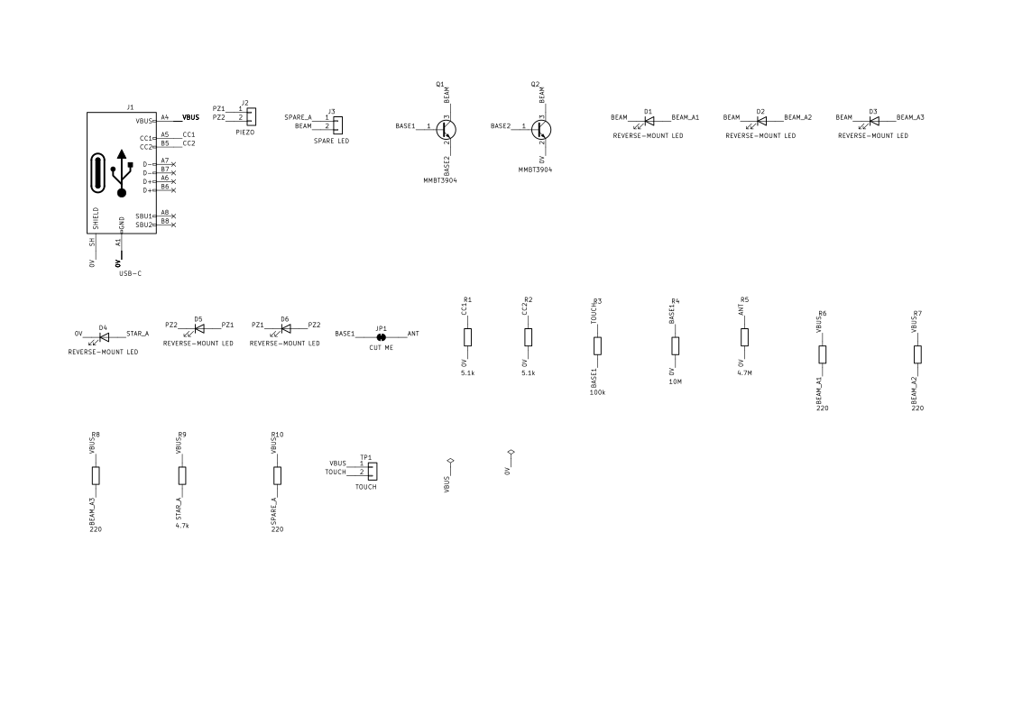
Drawing HULL-20-UFO-040 sheet 4: boarding pass rev B, assembly
| Item | Qty | Ref | Part | Package |
|---|---|---|---|---|
| 1 | 6 | D1, D2, D3, D4, D5, D6 | REVERSE-MOUNT LED | LED REVERSEMOUNT 1206 |
| 2 | 1 | J1 | USB-C | USB C RECEPTACLE 16P FLUSH |
| 3 | 2 | Q1, Q2 | MMBT3904 | SOT-23 |
| 4 | 2 | R1, R2 | 5.1K | R 0603 1608METRIC |
| 5 | 1 | R3 | 100K | R 0603 1608METRIC |
| 6 | 1 | R4 | 10M | R 0603 1608METRIC |
| 7 | 1 | R5 | 4.7M | R 0603 1608METRIC |
| 8 | 4 | R6, R7, R8, R10 | 220 | R 0603 1608METRIC |
| 9 | 1 | R9 | 4.7K | R 0603 1608METRIC |
Assembly notes
- Assembled on the bottom side, 100 boards. Positions from the placement file; reference designators as marked.
- Not assembled on purpose: J2 (piezo pads), J3 (spare LED pads), JP1 (jumper, cut to separate), TP1 (touch disc).
- D1 to D6 reverse-mount, bottom: the cathode mark on the pad the footprint marks K.
- Q1, Q2: pin 1 to the silk dot. J1 (USB-C): opening to the board edge.
- Unless otherwise specified
- DIMENSIONS IN MM
TOLERANCES: X.X ±0.2 X.XX ±0.1
PER IPC-6012 CLASS 2
DO NOT SCALE DRAWING - Drawn
- R. DIXON
- 2026-11-01
- Checked
- R. DIXON
- 2026-11-01
- Approved
- R. DIXON
- 2026-11-01
- Owner
- HULL/20
SPACEWAYS - Document type
- ASSEMBLY DRAWING
- Status
- ORDERED
- Units
- MM
- Projection
- THIRD ANGLE
PROJECTION - Title
- BOARDING PASS REV B, ASSEMBLY
- Size
- B
- Scale
- 1:1
- Sheet
- 4 OF 8
- Dwg no.
- HULL-20-UFO-040
- Rev
- B
Drawing HULL-20-UFO-040 sheet 5: boarding pass rev B, schematic
- Unless otherwise specified
- DIMENSIONS IN MM
TOLERANCES: X.X ±0.2 X.XX ±0.1
PER IPC-6012 CLASS 2
DO NOT SCALE DRAWING - Drawn
- R. DIXON
- 2026-11-01
- Checked
- R. DIXON
- 2026-11-01
- Approved
- R. DIXON
- 2026-11-01
- Owner
- HULL/20
SPACEWAYS - Document type
- SCHEMATIC
- Status
- ORDERED
- Units
- MM
- Projection
- THIRD ANGLE
PROJECTION - Title
- BOARDING PASS REV B, SCHEMATIC
- Size
- B
- Scale
- NONE
- Sheet
- 5 OF 8
- Dwg no.
- HULL-20-UFO-040
- Rev
- B
Drawing HULL-20-UFO-040 sheet 6: saucer badge rev A, fabrication
| Finished Ø | Holes | Plating |
|---|---|---|
| 0.30 | 234 | PTH |
| 0.65 | 2 | NPTH |
| TOTAL | 236 |
| Layer | Type | Thickness | Colour / material |
|---|---|---|---|
| F.SILKS | LEGEND | — | WHITE |
| F.MASK | SOLDER MASK | 0.01 | BLACK |
| F.CU | COPPER, 1 OZ | 0.035 | — |
| CORE | DIELECTRIC | TO SUIT | FR-4 |
| B.CU | COPPER, 1 OZ | 0.035 | — |
| B.MASK | SOLDER MASK | 0.01 | BLACK |
| B.SILKS | LEGEND | — | WHITE |
| FINISHED BOARD | 1.6 | ENIG |
Fabrication notes
Unless otherwise specified:
- Fabricate per IPC-6012 class 2; accept per IPC-A-600 class 2.
- FR-4, 2 layers, 1.6 finished thickness. Copper 1 oz (35 µm) outer, finished.
- Surface finish ENIG. Solder mask black both sides; legend white both sides. Vias tented.
- Hole sizes are finished sizes. Board outline per the Edge_Cuts layer; the outline governs.
- 100 % electrical test against the netlist. No fabricator marking on the board.
- The UFO-25 saucer at 1:24, an octagon 92.1 mm across the flats.
- The 0.30 holes are vias, tented. The two 0.65 NPTH holes locate the USB-C receptacle.
- Unless otherwise specified
- DIMENSIONS IN MM
TOLERANCES: X.X ±0.2 X.XX ±0.1
PER IPC-6012 CLASS 2
DO NOT SCALE DRAWING - Drawn
- R. DIXON
- 2026-11-01
- Checked
- R. DIXON
- 2026-11-01
- Approved
- R. DIXON
- 2026-11-01
- Owner
- HULL/20
SPACEWAYS - Document type
- FABRICATION DRAWING
- Status
- DESIGN
- Units
- MM
- Projection
- THIRD ANGLE
PROJECTION - Title
- SAUCER BADGE REV A, FABRICATION
- Size
- B
- Scale
- 1:1
- Sheet
- 6 OF 8
- Dwg no.
- HULL-20-UFO-040
- Rev
- B
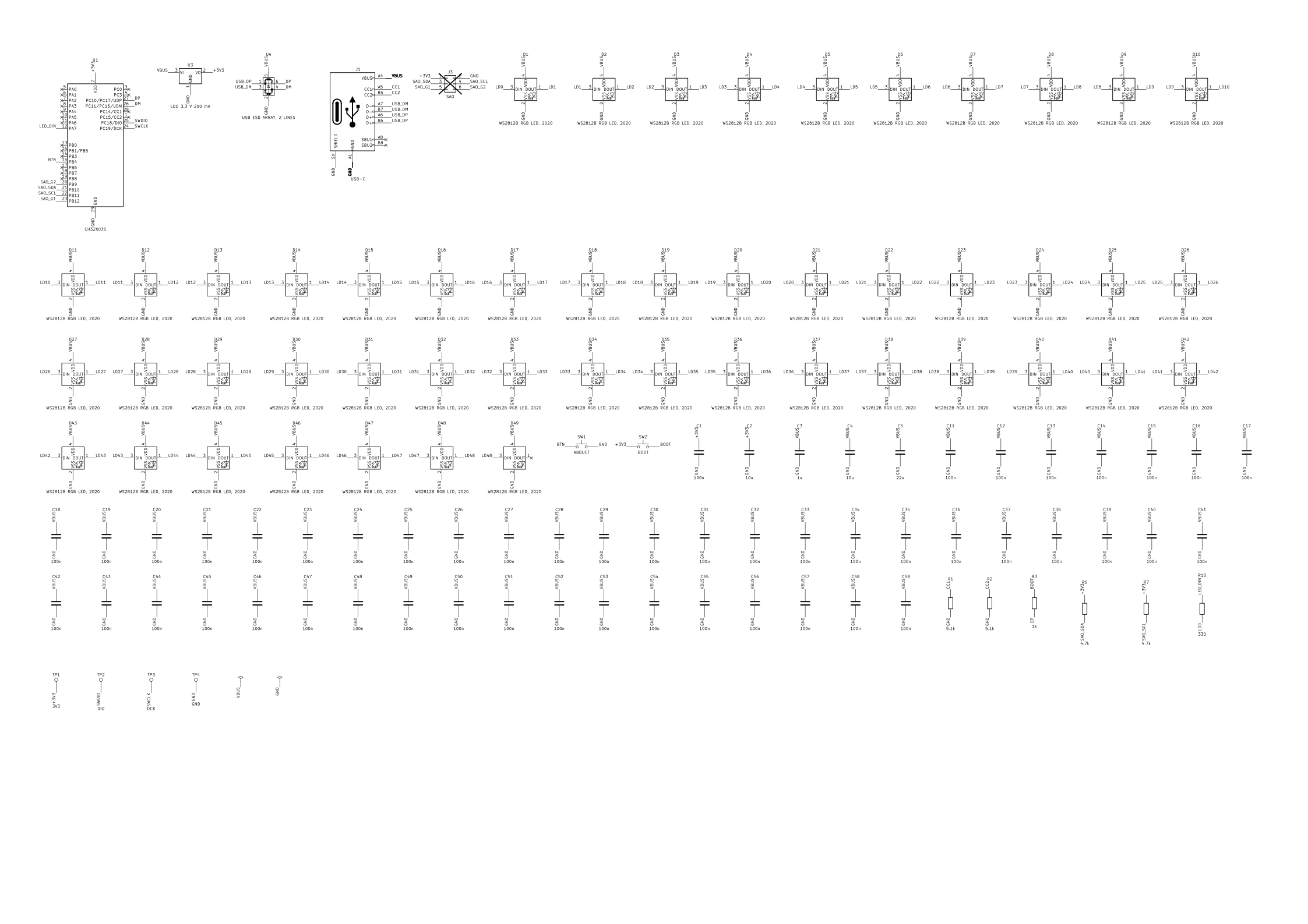
Drawing HULL-20-UFO-040 sheet 7: saucer badge rev A, assembly
| Item | Qty | Ref | Part | Package |
|---|---|---|---|---|
| 1 | 1 | C1 | 100N | C 0603 1608METRIC |
| 2 | 2 | C2, C4 | 10U | C 0603 1608METRIC |
| 3 | 1 | C3 | 1U | C 0603 1608METRIC |
| 4 | 1 | C5 | 22U | C 0805 2012METRIC |
| 5 | 49 | C11-C59 | 100N | C 0402 1005METRIC |
| 6 | 49 | D1-D49 | WS2812B RGB LED, 2020 | LED WS2812B-2020 PLCC4 2.0X2.0MM |
| 7 | 1 | J1 | USB-C | USB C RECEPTACLE 16P |
| 8 | 2 | R1-R2 | 5.1K | R 0603 1608METRIC |
| 9 | 1 | R3 | 1K | R 0603 1608METRIC |
| 10 | 2 | R6-R7 | 4.7K | R 0603 1608METRIC |
| 11 | 1 | R10 | 330 | R 0603 1608METRIC |
| 12 | 1 | SW1 | ABDUCT | SW PUSH 6X6X5MM |
| 13 | 1 | SW2 | BOOT | SW SPST SMD |
| 14 | 1 | U1 | CH32X035 | WQFN-28-1EP 4X4MM P0.4MM EP2.7X2.7MM |
| 15 | 1 | U3 | LDO 3.3 V 200 MA | SOT-23 |
| 16 | 1 | U4 | USB ESD ARRAY, 2 LINES | SOT-23-6 |
Assembly notes
- Assembled on the top side only: 115 parts from the placement file; reference designators as marked.
- Not assembled on purpose: J3 (add-on header pads, back) and TP1 to TP4 (debug pads, back).
- D1 to D49 are WS2812B RGB LEDs in the 2020 package. On the first article check pad 1 (DO) and the polarity mark on one rim, one porthole and the beam LED.
- LED chain: D1 to D32 the rim, clockwise from just west of the USB-C; D33 to D40 the hub, clockwise from the south spoke; D41 to D48 the portholes; D49 the beam.
- U1 pin 1 to the silk dot. J1 (USB-C) opening to the bottom edge. SW1 on the west edge.
- Firmware limits the LEDs to 400 mA; full white on all 49 would draw 735 mA.
- Unless otherwise specified
- DIMENSIONS IN MM
TOLERANCES: X.X ±0.2 X.XX ±0.1
PER IPC-6012 CLASS 2
DO NOT SCALE DRAWING - Drawn
- R. DIXON
- 2026-11-01
- Checked
- R. DIXON
- 2026-11-01
- Approved
- R. DIXON
- 2026-11-01
- Owner
- HULL/20
SPACEWAYS - Document type
- ASSEMBLY DRAWING
- Status
- DESIGN
- Units
- MM
- Projection
- THIRD ANGLE
PROJECTION - Title
- SAUCER BADGE REV A, ASSEMBLY
- Size
- B
- Scale
- 2:1
- Sheet
- 7 OF 8
- Dwg no.
- HULL-20-UFO-040
- Rev
- B
Drawing HULL-20-UFO-040 sheet 8: saucer badge rev A, schematic
- Unless otherwise specified
- DIMENSIONS IN MM
TOLERANCES: X.X ±0.2 X.XX ±0.1
PER IPC-6012 CLASS 2
DO NOT SCALE DRAWING - Drawn
- R. DIXON
- 2026-11-01
- Checked
- R. DIXON
- 2026-11-01
- Approved
- R. DIXON
- 2026-11-01
- Owner
- HULL/20
SPACEWAYS - Document type
- SCHEMATIC
- Status
- DESIGN
- Units
- MM
- Projection
- THIRD ANGLE
PROJECTION - Title
- SAUCER BADGE REV A, SCHEMATIC
- Size
- B
- Scale
- NONE
- Sheet
- 8 OF 8
- Dwg no.
- HULL-20-UFO-040
- Rev
- B